Учебники
Курсы высшего качества, чтобы стать экспертом
Файлы ресурсов
Требования
3DS Max 2010, Forest Pack Lite
Рекомендуемые продукты
Получить продуктыStriped lawn and ivy
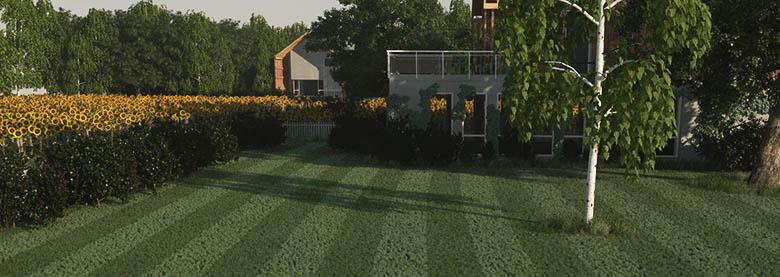
In this tutorial we will create a lawn with the characteristic stripes often seen when a mower with a heavy roller is used. This is caused by alternately bending the blades of grass in two opposing directions and affecting the way they reflect light. We will create this effect using a tiling gradient map to control the rotation of the grass geometry. By the end of this tutorial you should be able to:
- Use maps to control scale and rotation
The image below shows the effect a little clearer

- Create a new forest object using "spline_mowedGrass" as a distribution area and "wild grass" as a Custom Geometry object.
- Add the "large_barn" and "spline_road" as exclude areas.
- Set the Distribution Map to dense and Density to 5000mm. To increase the grass instances change the threshold to 10%
- Add "ground" as a Surface.
In order to use mapping to control transforms a surface is required. The UVW coordinates of the surface determine how the map is applied to the Forest object.
- This effect is easier to preview if we change the way the items display in the viewport. Go to the Display rollout, under the viewport settings choose proxy and pick pyramid from the drop down.
- To create the stripes go to the transform rollout and set the following settings:
Translation
X: 600%
Y: 20%
Z: 0%
Rotation
X minimum: -70 | X Maximum: 70
y minimum: -5 | y Maximum: 5
Z minimum: 0 | Z Maximum: 359
Scale
X minimum: 80 | X Maximum: 120
In the settings above the high percentage in the X translation setting is to break up the straight edges of the stripes.

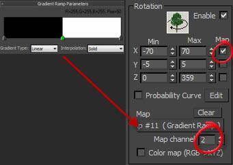
- To create the map open the material editor and create a new gradient ramp like the one show left.
- Drag this to the map Slot in the Rotation section of the Transform rollout.
- The Ground plane already has a separate map channel to control the tiling for the grass. To use it change the map channel to 2.
- To use the map to control the X Rotation tick the Use Map radio button.
- Render to test the effect.
When you are using greyscale maps to control transforms the black pixels represent the minimum value and black the maximum. If you wish to use a separate map for each axis then the red channel controls the X, green the Y, and blue the Z axis. You can find a handy tip for combining multiple black and white maps into a single RGB map using a composite texture in the Forest Pack Reference
Creating the ivy
In this section we will paint some ivy onto the side of the barn. This tutorial uses techniques we have already covered but demonstrates that forest pack is not restricted to scattering on a horizontal surface. This demonstration is very simple, but using forest in a vertical mode could be very useful for visualising dense walls of climbing plants and lush living or green walls.
- To get started create a new forest object using "ivy plane 1" as a surface. Add "ivy 1", "ivy 2", and "ivy 3" as custom objects.
When you create a forest object in generate mode, it aligns its axis to the local coordinate system of the first area selected. If you are in create mode it takes its axis from the active viewport.
We have readhed the end of the forest creation parts of this tutorial. In the final section we will adjust some materials using Forest Color.
- The leaves are too large. Set the Global Scale to 35%
- Set the Distribution Map to "dense" and the density to 4000mm. The threshold should be on about 10% - 15%.
- Enter the Transfrom settings as follows:
Rotation
X minimum: -20 | X Maximum: 20
y minimum: -44 | y Maximum: 10
Z minimum: -65 | Z Maximum: -120
Scale
X minimum: 80 | X Maximum: 120 - In the Areas rollout turn off the surface.
- Create a new paint area.
- Turn on paint and start brushing ivy around the windows. If you have a tablet you can use the pen pressure to vary the size of your paint brush for a more naturalistic effect.
